An inexpensive homebrew azimuth and elevation rotation system using an Arduino/AVR and the K3NG Arduino Rotator Controller code.
Updated 2020-01-01
Introduction
This project is a homebrew azimuth and elevation (“az/el”) rotation system using my Arduino rotator controller. This is not intended to be a complete step-by-step construction guide, but rather a description of how I built this in order to give you ideas for your own homebrew az/el project. This page is a work in progress and will continue to have additional information added in the near future. If you would like to discuss this project or have questions, please post them on the Radio Artisan group.
Project Description
The system uses a Yaesu G-1000DXA rotator unit for the azimuth and a cheap Radio Shack rotator for the elevation. The Yaesu rotator unit has a DC motor which operates on 12 to 24 volts DC. The Radio Shack rotator is an AC operated with a three terminal motor. You can substitute most any G series Yaesu rotator for the azimuth unit, as all that I have seen are DC operated. The Radio Shack rotator is a common one that is probably made in China and has been offered by many companies under many brand names, with a similar styled case for over 20 years. (Here’s a similar rotator). The rotator original control units are not used in this homebrew system; the controller supplies all voltages.
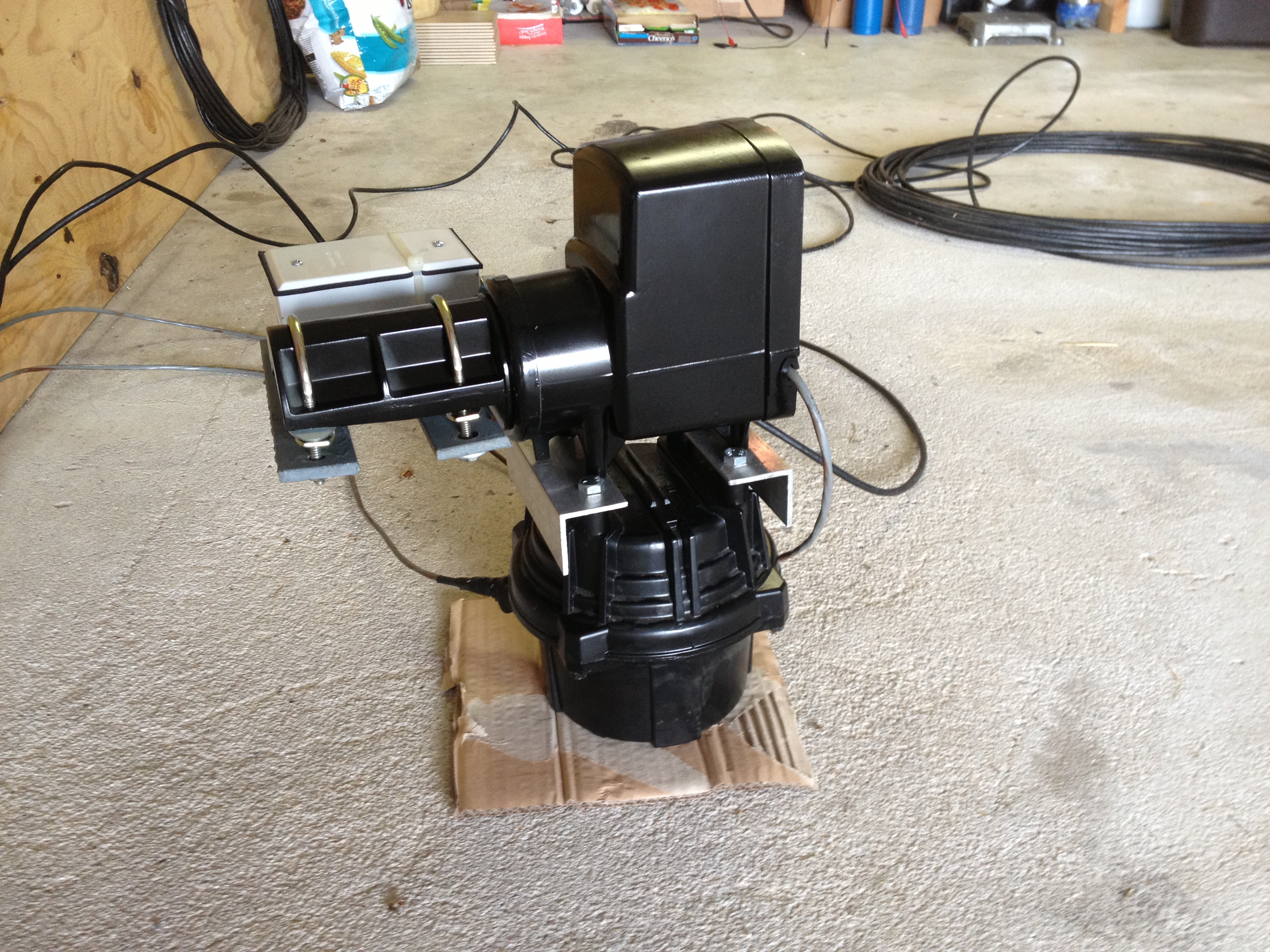
The azimuth and elevation rotation unit. The lower unit is the Yaesu azimuth rotator. The Radio Shack rotator used for elevation is mounted on top of the Yaesu rotator using aluminum L brackets and plastic spacers. The white box attached to the elevation rotator (on the left) is the remote slave unit, attached temporarily for testing purposes.

Side view of the rotator system. The remote slave unit is visible on the right.

Top view of the rotator system.
The azimuth heading is determined by the built-in potentiometer in the Yaesu rotator. The Radio Shack rotator has no such device internally to report the position, so an ADXL345 accelerometer is used to detect the elevation. The ADXL345 is an I2C device. The accelerometer must be mounted on the antenna boom in order to sense the elevation, however the I2C bus architecture does not have long distance capability. In order to interface with and read the accelerometer, a remote control unit or slave unit is located at the rotator. This remote unit also reads the voltage from the Yaesu rotator potentiometer to sense the azimuth heading. A master unit equipped with an Arduino Mega is located at the operating position and interfaces with a computer via the native USB interface. The remote unit is powered by a bare bones ATMega328, also running the Arduino rotator controller software operating in remote unit mode. The master and slave units communicate via a 9600 baud RS-232 serial link.

The master unit control board in testing on the bench.
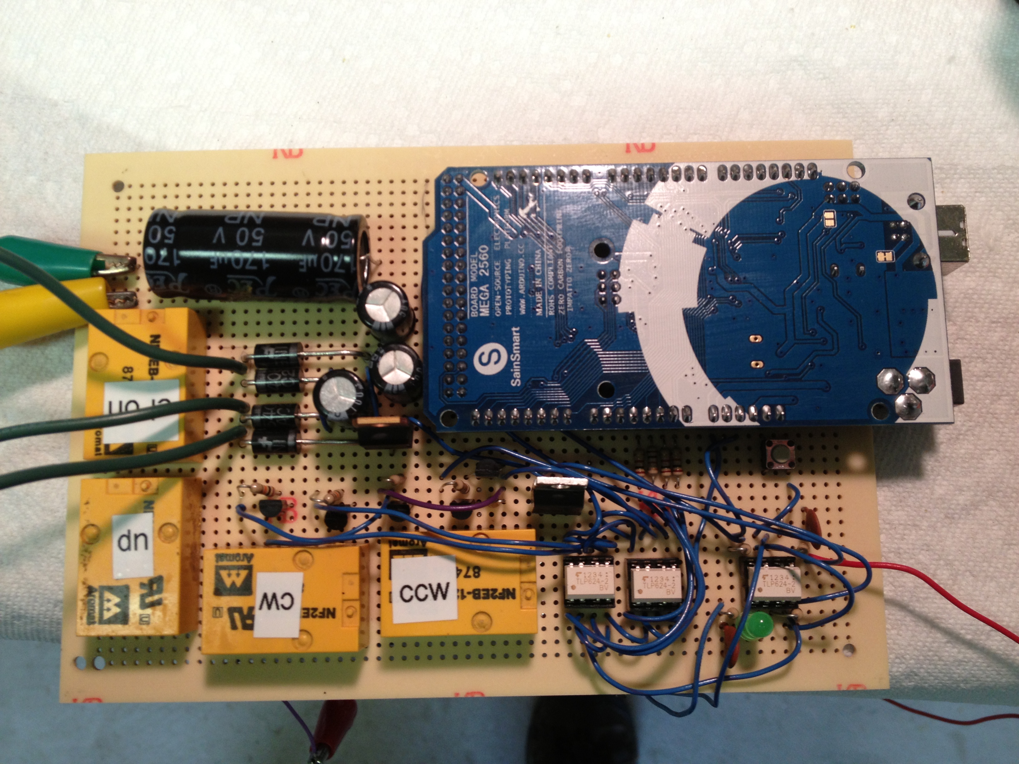
A closeup of the master unit control board, with the Arduino Mega. The green LED on the lower right indicates master/slave serial link activity. The master unit interfaces to a computer via the Arduino Mega USB port and emulates the Yaesu GS-232B protocol. The board supplies DC voltage to rotate the Yaesu azimuth rotator and 24 VAC to rotate the Radio Shack elevation rotator. The Mega is opto-isolated from the rest of the board, including the ground. The four relays in the lower left switch the DC and AC voltages.

This is the remote slave unit. It is in a waterproof box (a common outdoor electrical box from the local hardware store) that will be permanently mounted on the horizontal antenna mast connected to the elevation rotator. The remote slave unit talks to the master unit in the shack using a 9600 baud serial link. The remote slave reads the 0 to +5 volts azimuth voltage from the Yaesu rotator and reads the elevation via an I2C accelerometer module. The remote slave is periodically queried by the master unit and reports the azimuth and elevation.

The remote slave is powered by an ATMega328 AVR chip. The unit on the right is an ADXL345 I2C accelerometer which senses elevation. The remote slave interfaces to the master unit at the operating position via a nine conductor shielded cable. The red LED indicates power and the green LED blinks on and off ever second to indicate the microcontroller is “alive”.
Design Notes
The Arduino Mega is optically isolated from the rest of the control board. My original design did not include this, and I ended up installing opto-isolators after having issues with the Mega serial port resetting during elevation rotator AC power switching. Installing opto-isolators did not fix the issue, however I decided to keep the opto-isolators installed for good measure. The opto-isolators drive 2N2222 NPN transistors which in turn drive the relays. This is undoubtedly overkill as the opto-isolators themselves could easily drive the relays. This is a vestige of my original design and not necessary. The Mega is powered entirely via the USB port.
As I mentioned above, I had issues with the Arduino Mega (and Uno) USB port resetting during elevation rotator switching events. I spent days troubleshooting this issue. To make a very long story short, the ultimate fix was C15 and C16 on the master unit schematic.
I chose a Mega for the master control unit because it has multiple serial ports and I needed one for the communications link with the remote slave unit. Previously I experimented with Software Serial in other projects, but I had numerous problems with it. Hardware serial is just more reliable, so I went with that.
Schematics
Schematics in both PDF and KiCad format are located on Github.
Frankenrotator?
I called this Frankenrotator because it’s a Frankenstein creation of various parts lying around. :-)

2 thoughts on “Frankenrotator”
Comments are closed.